INTRODUCTION
Wavelength Dispersive X-Ray Fluorescence Spectrometry (WD-XRF) is the oldest method of measurement of X-rays, introduced commercially in the 1950’s. This name is descriptive in that the radiation emitted from the sample is collimated with a Soller collimator, and then impinges upon an analyzing crystal. The crystal diffracts the radiation to different extents, according to Bragg’s law, depending upon the wavelength or energy of the X radiation. This angular dispersion of the radiation permits the sequential or simultaneous detection of X-rays emitted by elements in the sample. Simultaneous instruments normally contain several sets of analyzing crystals and detectors; one is adjusted for each desired analyte in the sample. These instruments tend to be very expensive, but efficient for the routine determination or preselected elements.
WD-XRF spectrometers are usually larger and more expensive than other spectrometers. Because the analyzing crystal d-spacing determines wavelength sensitivity, they are usually more sensitive than other spectrometers. To overcome losses in X-ray optics of the WD-XRF spectrometers and to maximize primary radiation intensity, X-ray tubes are usually employed. The sample is usually held under vacuum to reduce contamination and avoid absorption of light element characteristic radiation in air.
Typical uses of WD-XRF include the analysis of oils and fuel, plastics, rubber and textiles, pharmaceutical products, foodstuffs, cosmetics and body care products, fertilizers, minerals, ores, rocks, sands, slags, cements, heat-resistant materials glass, ceramics, semiconductor wafers; the determination of coatings on paper, film, polyester and metals; the sorting or compositional analysis of metal alloys, glass and polymeric materials; and the monitoring of soil contamination, solid waste, effluent, cleaning fluids, sediments and air filters.
PRINCIPLE OF WD-XRF
WD-XRF spectrometers measure X-ray intensity as a function of wavelength. This is done by passing radiation emanating from the specimen through an analyzing diffraction crystal mounted on a 2θ goniometer. By Bragg’s Law, the angle between the sample and detector yields the wavelength of the radiation:
2d sin θ = nλ ;
where:
d is the d-spacing of the analyzing crystal,
θ is half the angle between the detector and the sample,
n is the order of diffraction.
The analyzing crystal must be oriented so that the crystal diffraction plane is directed in the appropriate direction. Figure shows a simplified schematic of the WD-XRF spectrometer. A scintillation or flow-proportional detector usually measures the fluoresced radiation. The heights of the resulting pulses are proportional to energy so using a pulse
 |
| 1. Schematic description of WD-XRF principle |
1. COLLIMATOR MASKS
The collimator masks are situated between the sample and collimator and serve the
purpose of cutting out the radiation coming from the edge of the cup aperture (Figure 2).
The size of the mask is generally adapted to suit of the cup aperture being used.
The masks perform one of the two functions: background reduction and improved
fluorescence (Figure 3).
 |
2.Use of Cu 200 μm filter for cutting off the radiation coming from Rh X-ray tube.
|
 |
3. Use of Al 100 μm filter for improvement of the ratio peak/background.
|
2. COLLIMATOR
 |
4. Collimators with different angles of resolution.
|
Collimators consist of a row of parallel slats (Figure 4) and select a parallel beam of X-rays coming from the sample and striking the crystal. The spaces between the slats determine the degree of parallelism and thus the angle resolution of the collimator.
A 0.077° collimator is adequate for high resolution measurement parameters. Collimators with low resolution (e.g. 1.5 -2.0°) are advantageous for light elements such as Be, B and C (Figure 5). Using a collimator with a low resolution increases then intensity significantly. This enables intensity to be increased without a loss in angle resolution when analyzing light elements.
 |
5. Example of the influence of collimator resolution on the intensity of a light
element.
|
3. THE ANALYZING CRYSTALS
a. Bragg’s Law
Crystals consist of a periodic arrangement of atoms (molecules) that form the crystal lattice. In such an arrangement of particles you generally find numerous planes running in different directions through the lattice points (= atoms, molecules), and not only horizontally and vertically but also diagonally. These are called lattice planes. All of the planes parallel to a lattice plane are also lattice planes and are at a defined distance from each other. This distance is called the lattice plane distance “d”.
 |
| 6. Bragg’s Law. |
When parallel X-ray light strikes a lattice plane, every particle within it acts as a scattering center and emits a secondary wave. All of the secondary waves combine to form a reflected wave. The same occurs on the parallel lattice planes for only very little of the X-ray wave is absorbed within the lattice plane distance “d”. All these reflected waves interfere with each other. If the amplification condition “phase difference = a whole multiple of the wavelength” (Δλ = nλ) is not precisely met, the reflected wave will interfere such that cancellation occurs. All that remains is the wavelength for which the amplification condition is met precisely. For a defined wavelength and a defined lattice plane distance, this is only given with a specific angle, the Bragg angle (Figure 6).
Under amplification conditions, parallel, coherent X-ray light (1,2) falls on a crystal
with a lattice plane distanced ‘d’ and is scattered below the angle θ (1′,2′). The proportion of the beam that is scattered on the second plane has a difference of ‘ACB’ to the proportion of the beam that was scattered at the first plane. The amplification condition is fulfilled when the phase difference is a whole multiple of the wavelength λ. This results in Bragg’s Law:
2d sin θ = nλ ;
n = 1, 2, 3… Reflection order.
On the basis of Bragg’s Law, by measuring the angle θ, we can determine either the
wavelength λ, and thus chemical elements, if the lattice plane distance ‘d’ is known or, if the wavelength λ is known, the lattice plane –value distance ‘d’ and thus the crystalline structure.
This provides the basis for two measuring techniques for the quantitative and qualitative determination of chemical elements (XRF) and crystalline structures (molecules, XRD), depending on whether the wavelength λ or the 2d-value is identified by measuring the angle θ.
- In X-ray diffraction (XRD) the sample is excited with monochromatic radiation of a known wavelength (λ) in order to evaluate the lattice plane distance as per Bragg’s equation.
- In XRF, the ‘d’-value of the analyzer crystal is known and we can solve Bragg’s equation for the element characteristic wavelength (λ).
b. Reflections of Higher Orders
Figures 7a and 7b illustrate the reflections of the first and second order of one wavelength below the different angles θ1 and θ2. Here, the total reflection is made up of the various reflection orders (1, 2 …, n). The higher the reflection order, the lower the intensity of the reflected proportion of radiation generally is. How great the maximum detectable order is depends on the wavelength, the type of crystal used and the angular range of the spectrometer.
 |
| 7 a. First order reflection: λ = 2 d sin θ1. |
 |
| 7 b. Second order reflection: 2λ = 2 d sin θ2. |
It can be seen from Bragg’s equation that the product of reflection orders ‘n = 1; 2; ..’
and wavelength ‘λ’ for greater orders, and shorter wavelengths ‘λ* < λ’ that satisfy the
condition ‘λ* = λ/n’, give the same result.
Accordingly, radiation with one half, one third, one quarter etc. of the appropriate
wavelength (using the same type of the crystal) is reflected below the identical angle θ:
1λ = 2(λ / 2) = 3(λ / 3) = 4(λ / 4) = ……......
As the radiation with one half of the wavelength has twice the energy, the radiation with one third of the wavelength three times the energy etc., peaks of twice, three times the energy etc. can occur in the pulse height spectrum (= energy spectrum) as long as appropriate radiation sources.
c. Crystal Types
The wavelength dispersive X-ray fluorescence technique can detect every element
above the atomic number 4 (Be). The wavelengths cover the range of values of four
magnitudes: 0.01 – 11.3 nm. As the angle θ can theoretically only be between 0° and 90° (in practice 2° to 75°), sinθ an only accept values between 0 and +1. When Bragg’s equation is applied:
0 < nλ/2d = Sinθ < 1
This means that the detectable element range is limited for a crystal with a lattice plane difference ‘d’. Therefore a variety of crystal type with different ‘2d’ values is necessary to detect the whole element range (from atomic number 4).
Besides the ‘2d’ values, the following selection criteria must be considered when a
particular type of crystal is to be used for a specific application:
- Resolution
- Reflectivity (→ intensity)
Further criteria can be:
- Temperature stability
- Suppression of higher orders
- Crystal fluorescence.
d. Dispersion, Line Separation
The extent of the change in angle Δθ upon changing the wavelength by the amount Δλ (thus: Δθ/Δλ) is called “dispersion”. The greater the dispersion, the better is the separation of two adjacent or overlapping peaks. Resolution is determined by the dispersion as well as by surface quality and the purity of the crystal.
Mathematically, the dispersion can be obtained from the differentiation of the Bragg
equation.
Δθ /Δλ = n/2dsinθ
It can be seen from this equation that the dispersion (or peak separation) increases as the lattice plane distance ‘d’ declines.
e. Synthetic Multilayers
 |
8. Diffraction in the layers (here: Si/W) of a multilayer.
|
Multilayers are not natural crystals but artificially produced ‘layer analyzers’. The lattice plane distances ‘d’ are produced by applying thin layers of two materials in alternation on to a substrate (Figure 8). Multilayers are characterized by high reflectivity and a somewhat reduced resolution. For the analysis of light elements the multilayer technique presents an almost revolutionary improvement for numerous applications in comparison to natural crystals with large lattice plane distances.
4. DETECTORS
When measuring X-ray, use is made of their ability to ionize atoms and molecules, i.e. to displace electrons from their bonds by energy transference. In suitable detector materials, pulses whose strengths are proportional to the energy of the respective X-ray quants are produced by the effect of X-ray. The information about the X-ray quarts energy is contained in the registration of the pulse height. The number of X-ray quants per unit of time, e.g. pulses per second (cps = counts per second, KCps = kilocounts per second), is called their intensity and contains in a first approximation the information about the concentration of the emitting in the sample. Two main types of detectors are used in wavelength dispersive X-ray fluorescence spectrometers: the gas proportional counter and the scintillation counter.
a. Gas Proportional Counter
 |
| 9: A gas proportional counter. |
The gas proportional counter comprises a cylindrical metallic tube in the middle of which a thin wire (counting wire) is mounted. This tube is filled with a suitable gas (e.g. Ar+ 10% CH4). A positive high voltage (+U) is applied the wire. The tube has a lateral aperture or window that is sealed with a material permeable to X-ray quants (Figure 9).
An X-ray quant penetrates the window into the counter’s gas chamber where it is absorbed by ionizing the gas atoms and molecules. The resultant positive ions move to the cathode (tube), the free electrons to the anode, the wire. The number of electron-ion pairs created is proportional to the energy of the X-ray quant. To produce an electron-ion pair,approx. 0.03 keV are necessary, i.e. the radiation of the element boron (0.185 keV) produces approx. 6 pairs and the K-alpha radiation of molybdenum (17.5 keV) produces approx. 583 pairs. Due to the cylinder geometric arrangement, the primary electrons created in this way see an increasing electrical field on route to the wire.
The high voltage in the counting tube is now set so high that the electrons can obtain enough energy from the electrical field in the vicinity of the wire to ionize additional gas particles. An individual electron can thus create up to 10.000 secondary electron-ion pairs. The secondary ions moving towards the cathode produce measurable signal. Without this process of gas amplification, signals from boron, for example, with 6 or molybdenum with 583 pairs of charges would not be able to be measured as they would not be sufficiently discernible from the electronic noise. As amplification is adjustable via high voltage in the counting tube and is set higher for measuring boron than for measuring molybdenum. The subsequent pulse electronics supply pulses of voltage whose height depends, amongst other factors, on the energy of the X-ray quants.
b. Scintillation Counters
 |
10. Scintillation counter including photomultiplier.
|
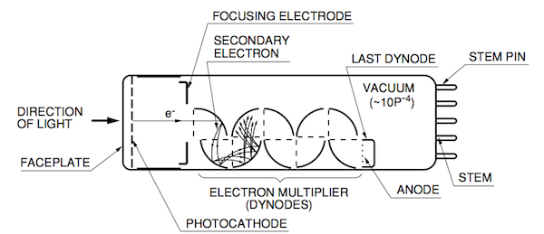
The scintillation counter, “SC”, used in XRF comprises a sodium iodide crystal in which thallium atoms are homogeneously distributed ‘NaI(Tl)’. The density of the crystal is sufficiently high to absorb all the XRF high energy quants. The energy of the pervading X-ray quants is transferred step by step to the crystal atoms that then radiate light and cumulatively produce a flash. The amount of light in this cintillation flash is proportional to the energy that the X-ray quant has passed to the crystal. The resulting light strikes a photocathode from which electrons can be detached very easily. These electrons are accelerated in a photomultiplier and, within an arrangement of dynodes, produce so-called secondary electrons giving a measurable signal once they have become a veritable avalanche (Figure 10). The height of the pulse of voltage produced is, as in the case of the gas proportional counter, proportional to the energy of the detected X-ray quant.
c. Pulse Height Analysis (PHA), Pulse Height Distribution
If the number of the measured pulses (intensity) dependent on the pulse height is displayed in a graph, we have the ‘pulse height spectrum’. Synonymous terms are: ‘pulse height analysis’ or ‘pulse height distribution’. As the height of the pulses of voltage is proportional to the X-ray quants energy, it is also referred to as the energy spectrum of the counter (Figure 11a and 11b). The pulse height is given in volts, scale divisions or in ‘%’ (and could be started in keV after appropriate calibration). The “%”-scale is defined in such a way that the peak to be to be analyzed appears at 100 %.
 |
11.a. Pulse height distribution
|
 |
11.b . Pulse height distribution (Fe) Scintillation counter.
|
 |
12. Pulse height distribution (Fe) with escape peak.
|
If argon is used as the counting gas component in gas proportional counters, an
additional peak, the escape peak (Figure 12), appears when X-ray energies are irradiated that are higher than the absorption edge of argon.
The escape peak arises as follows:
The incident X-ray quant passes its energy to the counting gas thereby displaying a K electron from an argon atom. The Ar atom can now emit an Ar Kα1,2 X-ray quant with an energy of 3 keV. If this Ar-fluorescence escapes from the counter then only the incident energy minus 3 keV remains for the measured signal. A second peak, the escape peak that is always 3 keV below the incident energy, appears in the pulse height distribution.
When using other counting gases (Ne, Kr, Xe) instead of argon, the escape peaks appear with an energy difference below the incident energy that is equivalent to the appropriate emitted fluorescence radiation (Kr, Xe). Using neon as the counting gas component produces no recognizable escape peak as the Ne K-radiation, with energy of 0.85 keV, is almost completely absorbed in the counter. Also, the energy difference to the incident of 0.85 keV and the fluorescence yield are very small.