Showing posts with label sensor. Show all posts

Friday, 22 May 2015

PORTABLE PHOTOSYNTHESIS SYSTEM : MEASUREMENT PRINCIPLE

MEASUREMENT THEORY

The PHOTOSYNTHESIS SYSTEM is a completely self-contained unit for measuring the CO2 assimilation (Photosynthesis and Respiration) and transpiration (water loss by evaporation of leaves of plants. These systems are designed specifically for use by students in Schools and Universities. It offers many of the facilities of instruments designed for research , but greatly simplifies the measurement procedure.
 
It operates on the Open System principle. The leaf is placed in a sealed enclosure with a window for illumination. This is referred to as the leaf cuvette. Through the cuvette is passed a measured flow of air. The CO2 / H2O concentrations of the air entering (reference air) and of the air leaving (analysis air) are measured. To measure the concentrations the PHOTOSYNTHESIS SYSTEM uses a single CO2 and H2O sensor and alternately switches the reference and analysis air. From the flow rate of air and the change in the concentration the assimilation and transpiration rates are calculated.

Though it is designed to supply ambient air to the cuvette, for the study of CO2 responses, it is possible to decrease the CO2 concentration in a series of steps. A similar provision is made for water vapour responses. It is supplied with a leaf cuvette which can be used for a wide variety of leaves. A light unit will be available shortly (LED) for use with the cuvette for manual control of cuvette light intensity.

CO2 /H2O ANALYSIS MEASUREMENT PRINCIPLE

Carbon Dioxide absorbs Infra-red radiation strongly at a wavelength of 4.26 microns. PHOTOSYNTHESIS SYSTEM uses this absorption to measure the CO2 concentration. The analyzer consists of a source of infra-red radiation (a small tungsten filament lamp) at one end of a highly polished, gold plated tube through which the air passes. At the other end of the tube is the infra-red detector which has a window through which only infra-red radiation at 4.26 microns can pass so that the responds only to the presence of CO2. The theoretical analysis range is from 0-100% CO2. However, because of the absorption characteristics of gases, the absorption path lengths, infrared source intensities, detector sensitivities and the S/N (Signal to Noise) ratio of the system define the effective range. The absorption path length of PHOTOSYNTHESIS SYSTEM is optimised for 2,000 volumes of CO2 per million volumes of air. This is correctly referred to as 2000 parts per million by volume or 2000 ppm. (Ambient air contains about 360 ppm.).
Temperature corrections are not required as the opto-electronics are thermostatted and the air is equilibrated to this temperature before entering the absorption cells. The built in transducer compensates for absolute pressure changes in the cell.
In part, the excellent stability of PHOTOSYNTHESIS SYSTEM is due to regular zeroing when CO2 free, air is passed through (referred to as ZERO). ZERO minimises the effects on span (gas sensitivity), of sample cell contamination, source ageing, and changes in detector sensitivity, amplifier gains, and reference voltages. It is done every approximately minute. The ZERO reading is used to compensate for changes in the signal level. From the relationship between absorptance and concentration, determined in the factory, and the current calibration factor, the sample concentration is determined.

Water vapor is measured using a high precision capacitive sensor. This consists of a small piece of glass coated first with a layer of metal, then with a polymer, followed by a second metal layer. Wires are soldered to the metal layers and the sensor is placed in a circuit that measures its electrical capacitance. The amount of water in the polymer depends on the water vapour content of the air and the electrical capacitance of the polymer depends on the water content. So with calibration, the water in the air can be measured. Water vapour concentration is again expressed as a volume/volume relationship but in parts per thousand, which is called millibars (mb)

Both CO2 and H2O measurements give the absolute concentrations for the reference air, and then the difference between the reference and the analysis concentration.
The complete PHOTOSYNTHESIS SYSTEM gas circuit with control valves is shown below.


Monday, 9 February 2015

LASER INDUCED BREAKDOWN SPECTROSCOPY


LIBS, is a spectroscopy technique in which a short laser pulse beam is focused on a target sample. Laser energy ionizes the sample material by heating it,  creating small area of plasma. Excited ions in the plasma state emits light waves which are collected and the spectrum is resolved by a spectrometer and analyzed by suitably calibrated  photon or light detector. Each chemical element has a unique wavelength or signature which can be optically resolved from the obtained spectrum. As  result, the composition of the elements which constitutes in the target sample can be determined. Below provided some of the general information about the technique :

i Advantages
ii Considerations
  • Spectral coverage vs. resolution
  • Light sensitivity
iii. General Applications


I. Advantages


LIBS is considered one of the most  efficient and user friendly analytical techniques for trace elemental analysis in gases, solids, and liquids. Some of its major advantages include:
  • Real-time measurements: online monitoring and quality control of industrial processes
  • Noninvasive, nondestructive technique: valuable samples can be reused, sensitive materials can be analyzed, suitable for in-situ biological analysis
  • Remote measurements can be done from up to 50 meters distance: can be used in hazardous environments and for space exploration missions on other planets
  • Compact and inexpensive equipment: can be widely used in industrial environments, perfect for field measurements
  • High-spatial resolution: can obtain 2D chemical and mechanical profiles of virtually any solid material with up to 1 µm precision
  • Non or very little sample preparation is required: reduced measurement time, greater convenience, less opportunity for sample contamination
  • Samples can be in virtually any form: gas, liquid, or solids
  • Analysis can be performed with a very small amount of sample (nanograms): very useful in chemistry for characterization of new chemicals and in material science for characterization of new composite materials or nanostructures
  • Virtually any chemical element can be analyzed, such as heavier elements unavailable for X-ray fluorescence
  • Analysis can be done on extremely hard materials like ceramics and superconductors; these materials are difficult to dissolve or sample to perform other types of analysis
  • In aerosols both particle size and chemical composition can be analyzed simultaneously
II. Considerations
  •  Spectral Coverage vs. Resolution

Compact echelle spectrometers designed for LIBS applications are offered by several manufacturers.
In the rare occasion that an application requires even higher resolution, the Acton Series of spectrometers with their long focal lengths are extremely useful. The latest models  use toroid mirrors with improved spectral quality.
For a  detector with 1024 horizontal pixels, each of which is 26 m wide, the theoretical field of view is 26.6 mm. But since a standard 25 mm intensifier is used, the field of view is 25 mm.
For example, if you decided to utilize a 2400 groove/mm grating in the Acton Series 2500 in order to enhance resolution, the linear dispersion will be 0.6 nm/mm while the spectral coverage will be 0.6*25 = 15 nm. To cover a spectral range between 300 and 600 nm (for example), you will need to perform at least 20 laser shots each time, moving the spectrometer grating to a new position and "gluing" all 20 spectra together. This is a very standard procedure which can be done painlessly and automatically
.
The only disadvantage to this is that acquisition of one spectrum could take up to a few dozen seconds or longer, which is why the echelle spectrometer has become extremely popular, especially in industrial and field applications where real-time measurements such as online quality control is a must.

  •  Light sensitivity

Typically, the laser pulse in LIBS applications lasts for femto- to nanoseconds (10-15 to 10-9 s). Especially in applications where non-invasive and non-destructive analysis is required, a relatively small amount of laser energy is transferred to the sample. Therefore, one laser pulse produces a weak emission signal which is hard or impossible to collect with conventional CCD detectors. That is why intensified CCDs (ICCDs) are widely used in LIBS.
To improve the emitting signal on the order of 10-30 times, a scheme with two orthogonal lasers beams is often used. In this dual-scheme, the first and usually more powerful laser pulse ablates and atomizes sample material while the second one heats the ablated material even further, allowing it to improve the intensity of atomic or ionic lines. Factors such as the level of laser excitation energy for both pulses and the time delay between the pulses play a crucial role in achieving signal intensity enhancement. This technique increases the sensitivity of LIBS by  at least one order of magnitude and allows for a greater possible number of applications.
If measurement time duration is not an issue, a regular CCD, (1024x1024 pixels, 13 µm pixel size), can be used together with the an spectrometer for LIBS applications. To obtain the reasonable light level required for a non-intensified CCD, long exposure time measurements should be performed. In this case, plasma emission signal is accumulated on the CCD from a multiple laser pulse. However, one should be careful about excessive accumulation of background noise and low signal-to-noise ratio. It is especially important when performing measurements in the open air without an enclosed sample chamber. Since the CCD stays open for a long period of time, all sources of stray light in the room should be eliminated and measurements should be conducted in darkness.  CCD usually proves a more sophisticated system than the  ICCD because intensified CCDs are prone to permanent damage by excessive light levels. Extra care should be taken so as not to expose ICCDs to the bright sources of light like laser reflections. In the case of a regular CCD, it is difficult to damage with excessive light.

III. General Applications

The fact that LIBS generally requires little-to-no sample preparation, simple instrumentation, and can easily be performed on-the-field in hazardous industrial environments in real-time, it is a very attractive analytical tool. The following are a few examples of real life applications, where LIBS is successfully used:
  • Express-analysis of soils and minerals (geology, mining, construction)
  • Exploration of planets (such as projects using LIBS for analyzing specific conditions on Mars and Venus to understand their elemental composition)
  • Environmental monitoring (Real-time analysis of air and water quality, control of industrial sewage and exhaust gas emissions)
  • Biological samples (non-invasive analysis of human hair and teeth for metal poisoning, cancer tissue diagnosis, bacteria type detection, detection of bio-aerosols and bio-hazards, anthrax, airborne infectious disease, viruses, sources of allergy, fungal spores, pollen). Replacing antibody, cultural, and DNA types of analysis
  • Archeology (analysis of artifacts restoration quality)
  • Architecture (quality control of stone buildings and glasses restoration)
  • Army and Defense (detection of biological weapons, explosives, backpack-based detection systems for homeland security)
  • Forensic (gun shooter detection)
  • Combustion processes (analysis of intermediate combustion agents, combustion products, furnace gases control, control of unburned ashes)
  • Metal industry (in-situ metal melting control, control of steel sheets quality, 2D mapping of Al alloys)
  • Nuclear industry (detection of cerium in U-matrix, radioactive waste disposal)

Monday, 20 May 2013

PHOTOMULTIPLIER TUBE


INTRODUCTION

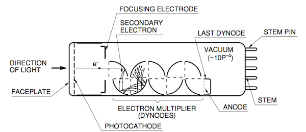
Among the photosensitive devices in use today, the photomultiplier tube (or PMT) is a versatile device that provides extremely high sensitivity and ultra-fast response. A typical photomultiplier tube consists of a photoemissive cathode (photocathode) followed by focusing electrodes, an electron multiplier and an electron collector (anode) in a vacuum tube.When light enters the photocathode, the photocathode emits photoelectrons into the vacuum. These photoelectrons are then directed by the focusing electrode voltages towards the electron multiplier where electrons are multiplied by the process of secondary emission. The multiplied electrons are collected by the anode as an output signal. Because of secondary-emission multiplication, photomultiplier tubes provide extremely high sensitivity and exceptionally low noise among the photosensitive devices currently used to detect radiant energy in the ultraviolet, visible, and near infrared regions. The photomultiplier tube also features fast time response, low noise and a choice of large photosensitive areas.


HISTORY

In 1935, Iams  succeeded in producing a triode photomultiplier tube with a photocathode combined with a single-stage dynode (Secondary emissive surface), which was used for movie sound pickup. In the next year 1936, Zworykin  developed a photomultiplier tube having multiple dynode stages. This tube enabled electrons to travel in the tube by using an electric field and a magnetic field.Then, in 1939, Zworykin and Rajchman developed an electrostatic-focusing type photomultiplier tube (this is the basic structure of photomultiplier tubes currently used). In this photomultiplier tube, an Ag-O-Cs photocathode was first used and later an Sb-Cs photocathode was employed.An improved photomultiplier tube structure was developed and announced by Morton in 1949) and in 1956. Since then the dynode structure has been intensively studied, leading to the development of a variety of dynode structures including circular-cage, linear-focused and box-and-grid types. In addition, photomultiplier tubes using magnetic-focusing type multipliers transmission-mode secondary-emissive surfaces and channel type multipliers have been developed.

CONSTRUCTION

A photomultiplier tube is a vacuum tube consisting of an input window, a photocathode, focusing electrodes, an electron multiplier and an anode usually sealed into an evacuated glass tube. Figure shows the schematic construction of a photomultiplier tube.


Light which enters a photomultiplier tube is detected and produces an output signal through the following processes.
(1) Light passes through the input window.
(2) Light excites the electrons in the photocathode so that photoelectrons are emitted into the vacuum (external photoelectric effect).
(3) Photoelectrons are accelerated and focused by the focusing electrode onto the first dynode where they are multiplied by means of secondary electron emission. This secondary emission is repeated at each of the successive dynodes.
(4) The multiplied secondary electrons emitted from the last dynode are finally collected by the anode.

The photomultiplier tube generally has a photocathode in either a side-on or a head-on configuration. The side-on type receives incident light through the side of the glass bulb, while in the head-on type, it is received through the end of the glass bulb. In general, the side-on type photomultiplier tube is relatively low priced and widely used for spectrophotometers and general photometric systems. Most of the side-on types employ an opaque photocathode (reflection-mode photocathode) and a circular cage structure electron multiplier which has good sensitivity and high amplification at a relatively low supply voltage.

The head-on type (or the end-on type) has a semi transparent photocathode (transmission-mode photocathode) deposited upon the inner surface of the entrance window.
The head-on type provides better spatial uniformity than the side-on type having a reflection-mode photocathode. Other features of head-on types include a choice of photosensitive areas from tens of square millimetres to hundreds of square centimetres .
Variants of the head-on type having a large-diameter hemispherical window have been developed for high energy physics experiments where good angular light acceptability is important. 


External appearance 


Types of Photocathode


WORKING

The superior sensitivity (high current amplification and high S/N ratio) of photomultiplier tubes is due to the use of a low-noise electron multiplier which amplifies electrons by a cascade secondary electron emission process. The electron multiplier consists of from 8, up to 19 stages of electrodes called dynodes.There are several principal types in use today.

1) Circular-cage type
The circular-cage is generally used for the side-on type of photomultiplier tube. The prime features of the circular-cage are compactness and fast time response.


2) Box-and-grid type
This type consists of a train of quarter cylindrical dynodes and is widely used in head-on type photomultiplier tubes because of its relatively simple dynode design and improved uniformity, although time response may be too slow in some applications.


3) Linear-focused type
The linear-focused type features extremely fast response time and is widely used in head-on type photomultiplier tubes where time resolution and pulse linearity are important.


4) Venetian blind type
The venetian blind type has a large dynode area and is primarily used for tubes with large photocathode areas. It offers better uniformity and a larger pulse output current. This structure is usually used when time response is not a prime consideration.

5) Mesh type
The mesh type has a structure of fine mesh electrodes stacked in close proximity. This type provides high immunity to magnetic fields, as well as good uniformity and high pulse linearity. In addition, it has position-sensitive capability when used with cross-wire anodes or multiple anodes.


6) Microchannel plate (MCP)
The MCP is a thin disk consisting of millions of micro glass tubes (channels) fused in parallel with each other. Each channel acts as an independent electron multiplier. The MCP offers much faster time response than the other discrete dynodes.It also features good immunity from magnetic fields and two-dimensional detection ability when multiple anodes are used.


7) Metal channel type
The Metal channel dynode has a compact dynode costruction manufactured by our unique fine machining technique.It achieves high speed response due to its narrower space between each stage of dynodes than the other type of conventional dynode construction. It is also adequate for position sensitive measurement.


PHOTOCATHODE MATERIALS

The photocathode is a photoemissive surface usually consisting of alkali metals with very low work functions. The photocathode materials most commonly used in photomultiplier tubes are as follows:

1) Ag-O-Cs
The transmission-mode photocathode using this material is designated S-1 and sensitive from the visible to infrared range (300 to 1200nm). Since Ag-O-Cs has comparatively high thermionic dark emission, tubes of this photocathode are mainly used for detection in the near infrared region with the photocathode cooled.

2) GaAs(Cs)
GaAs activated in cesium is also used as a photocathode. The spectral response of this photocathode usually covers a wider spectral response range than multi alkali, from ultraviolet to 930nm, which is comparatively flat over 300 to 850nm.

3) InGaAs(Cs)
This photocathode has greater extended sensitivity in the infrared range than GaAs. Moreover, in the range between 900 and 1000nm, InGaAs has much higher S/N ratio than Ag-O-Cs.

4) Sb-Cs
This is a widely used photocathode and has a spectral response in the ultraviolet to visible range. This is not suited for transmission-mode photocathodes and mainly used for reflection-mode photocathodes.

5) Bialkali (Sb-Rb-Cs, Sb-K-Cs)
These have a spectral response range similar to the Sb-Cs photocathode, but have higher sensitivity and lower noise than Sb-Cs. The transmission mode bialkali photocathodes also have a favorable blue sensitivity for scintillator flashes from NaI (Tl) scintillators, thus are frequently used for radiation measurement using scintillation counting.

6) High temperature bialkali or low noise bialkali (Na-K-Sb)
This is particularly useful at higher operating temperatures since it can withstand up to 175°C. A major application is in the oil well logging industry. At room temperatures, this photocathode operates with very low dark current, making it ideal for use in photon counting applications.

7) Multialkali (Na-K-Sb-Cs)
The multialkali photocathode has a high, wide spectral response from the ultraviolet to near infrared region. It is widely used for broad-band spectrophotometers. The long wavelength response can be extended out to 930nm by special photocathode processing.

8) Cs-Te, Cs-I
These materials are sensitive to vacuum UV and UV rays but not to visible light and are therefore called solar blind. Cs-Te is quite insensitive to wavelengths longer than 320nm,and Cs-I to those longer than 200nm.

WINDOW MATERIALS
The window materials commonly used in photomultiplier tubes are as follows:

1) Borosilicate glass
This is frequently used glass material. It transmits radiation from the near infrared to approximately 300nm. It is not suitable for detection in the ultraviolet region. For some applications,the combination of a bialkali photocathode and a low-noise borosilicate glass (so called K-free glass) is used.The K-free glass contains very low potassium (K2O) which can cause background counts by 40K. In particular, tubes designed for scintillation counting often employ K-free glass not only for the faceplate but also for the side bulb to minimize noise pulses.

2) UV-transmitting glass (UV glass)
This glass transmits ultraviolet radiation well, as the name implies, and is widely used as a borosilicate glass. For spectroscopy applications, UV glass is commonly used. The UV cut-off is approximately 185nm.

3) Synthetic silica
The synthetic silica transmits ultraviolet radiation down to 160nm and offers lower absorption in the ultraviolet range compared to fused silica. Since thermal expansion coefficient of the synthetic silica is different from Kovar which is used for the tube leads, it is not suitable for the stem material of the tube . Borosilicate glass is used for
the stem, then a graded seal using glasses with gradually different thermal expansion coefficients are connected to the synthetic silica window. Because of this structure, the graded seal is vulnerable to mechanical shock so that sufficient care should be taken in handling the tube.

4) MgF2 (magnesium fluoride)
The crystals of alkali halide are superior in transmitting ultraviolet radiation, but have the disadvantage of deliquescence. Among these, MgF2 is known as a practical window material because it offers low deliquescence and transmits ultraviolet radiation down to 115nm.


SCINTILLATION COUNTING


Scintillation counting is one of the most sensitive and effective methods for detecting radiation. It uses a photomultiplier tube coupled to a transparent crystal called scintillator which produces light by incidence of radiation.
 In radiation measurements, there are two parameters that should be measured. One is the energy of individual particles and the other is the amount of particles. Radiation measurements should determine these two parameters.
When radiation enters the scintillator, it produce light flashes in response to each particle. The amount of flash is proportional to the energy of the incident racliation. The photomultiplier tube detects individual light flashes and provides the output pulses which contain information on both the energy and amount of pulses, as shown in Figure . By analyzing these output pulses using a multichannel analyzer (MCA), a pulse height distribution (PHD) or energy spectrum is obtained, and the amount of incident particles at various energy levels can be measured accurately.
Typical PHDs or energy spectra when gamma rays (55Fe, 137Cs, 60Co) are detected by the combination of an NaI(Tl) scintillator and a photomultiplier tube. For the PHD,it is very important to have distinct peaks at each energy level.This is evaluated as pulse height resolution (energy resolution)and is the most significant characteristic in radiation particle measurements.

References :

1. Photomultipier tubes basics and application (third edition), HAMAMATSU
2. Photomultiplier tubes construction and operating characteristics,HAMAMATSU