Showing posts with label photomultiplier. Show all posts

Tuesday, 24 February 2015

DIFFERENCE BETWEEN PHOTOMULTIPLIER (PMT) & CHARGED COUPLED DEVICE (CCD) DETECTORS

Some of the most common differences between Photo multiplier (PMT) detectors & Charged Coupled Device detector (CCDs)..


1.       Photomultiplier tubes (PMTs) and Charged coupled devices (CCDs) both give spectra. The difference is the PMT is used with a small slit in front of it to control the bandwidth of light being detected. The CCD takes advantage of the dispersed light fully. The pixel columns will each correspond to a wavelength (resolution and range depend on the grating used). A PMT requires scanning of the Monochromator to collect a spectra. The CCD takes a single snap shot and you have a spectrum. The CCD sensitivity and dynamic range is lower than a PMT.


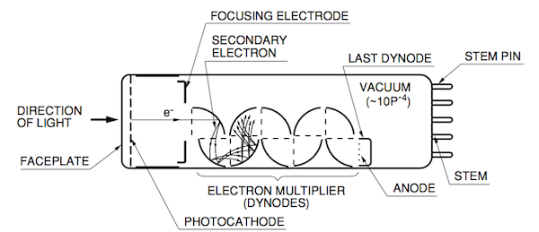
2.     A photomultiplier tube is a detection device that is made from a glass vacuum tube with a series of metal plate electrodes. A CCD is a solid state detector made from semiconductor materials.


3.     The main difference is one of sensitivity. Generally speaking the better the spectral resolution of the instrument the lower the amount of light reaching the detector and so you need more sensitivity in your detector. A PMT measures a single point in the spectrum at a time whereas with a CCD the complete spectrum is imaged across the CCD and so can be measured all at the same time. 


4.     An instrument with a CCD is usually much faster and cheaper but will not have as good a spectral resolution (the ability to resolve absorbance peaks very close to each other).


5.     CCDs and photomultipliers vary in a number of aspects. One difference is gain, a photomultiplier has gain whereas a CCD does not (hence the multiplier bit of PMT). The PMT gain may be up to 10,000,000 and is available at high speeds and for large area detectors, which means that one can usually get close to the theoretical noise floor. On the other hand, PMTs have poor quantum efficiency compared to CCDs (25% typ against 85% typ) so you can sometimes get better performance with a CCD if you can go slowly enough.


6.     PMTs are also typically single channel devices, although 16 channel linear arrays are available. CCDs are usually linear or 2D arrays.


7.     In a dispersive spectrometer a linear CCD array can capture the entire spectrum in one measurement. A single channel PMT must have the spectrum scanned across it sequentially to produce the entire spectrum.


8.     PMT's are typically preferable to CCD's on spectroscopic application for several reasons. The ability to adjust the gain of each PMT allows a manufacturer to adjust the response of each PMT to the specific signal being measured, so every element you are trying to detect can be analyzed at optimum conditions. Solid state CCD's are a compromise. Every element detected has the same conditions, so most are compromised. 


9.     Also, PMT's can be heated and held at constant temperature (in well made instruments) to prevent drift caused by variation in temperature. If you try to heat a CCD, the noise level will go up, and the signal to noie ratio will degrade as a result. CCD's are sometimes cooled to try to improve their s/n ratio, but usually not cooled enough to really help much due to condensation issues that arise. 


10. A third advantage of PMT's is that they can be used in a vacuum chamber without long term degradation for decades of use. The surface of a CCD will degrade under vacuum over a few (8-15) years. Most manufacturers making CCD based instruments opt for a Nitrogen or Argon flush, rather than vacuum to displace the oxygen from the detector chamber. This method results in decreased performance compared to PMT's, and is used in lower performance less expensive spectrometers.

Thursday, 13 June 2013

INDUCTIVE COUPLED PLASMA OPTICAL EMISSION SPECTROMETER

INTRODUCTION

ICP/OES is one of the most powerful and popular analytical tools for the determination of trace elements in a sample types. The technique is based upon the spontaneous emission of photons from atoms and ions that have been excited in a RF discharge. Liquid and gas samples may be injected directly into the instrument, while solid samples require extraction or acid digestion so that the analytes will be present in a solution. The sample solution is converted to an aerosol and directed into the central channel of the plasma. At its core the inductively coupled plasma (ICP) sustains a temperature of approximately 10 000 K, so the aerosol is quickly vaporized. Analyte elements are liberated as free atoms in the gaseous state. Further collisional excitation within the plasma imparts additional energy to the atoms, promoting them to excited states. Sufficient energy is often available to convert the atoms to ions and subsequently promote the ions to excited states. Both the atomic and ionic excited state species may then relax to the ground state via the emission of a photon. These photons have characteristic energies that are determined by the quantized energy level structure for the atoms or ions. Thus the wavelength of the photons can be used to identify the elements from which they originated. The total number of photons is directly proportional to the concentration of the originating element in the sample.The instrumentation associated with an ICP/OES system is relatively simple. A portion of the photons emitted by the ICP is collected with a lens or a concave mirror. This focusing optic forms an image of the ICP on the entrance aperture of a wavelength selection device such as a monochromator. The particular wavelength exiting the monochromator is converted to an electrical signal by a photo detector. The signal is amplified and processed by the detector electronics, then displayed and stored by a computer.


ICP OES OPERATION 

As shown in Figure, the so-called ICP ‘‘torch’’ is usually an assembly of three concentric fused-silica tubes. These are frequently referred to as the outer, intermediate, and inner gas tubes. The diameter of the outer tube ranges from 9 to 27 mm. A water-cooled, two- or three-turn copper coil, called the load coil, surrounds the top section of the torch, and is connected to a RF generator. The outer argon flow (10–15 L min) sustains the high temperature plasma, and positions the plasma relative to the outer walls and the induction coil, preventing the walls from melting and facilitating the observation of emission signals. The plasma under these conditions has an annular shape. The sample aerosol carried by the inner argon flow (0.5–1.5 Lmin) enters the central channel of the plasma and helps to sustain the shape. The intermediate argon flow (0–1.5 Lmin) is optional and has the function of lifting the plasma slightly and diluting the inner gas flow in the presence of organic solvents.

The ICP is generated as follows. RF power, typically 700–1500 W, is applied to the load coil and an alternating current oscillates inside the coil at a rate corresponding to the frequency of the RF generator. For most ICP/OES instruments, the RF generator has a frequency of either 27 or 40 MHz. The oscillation of the current at this high frequency causes the same high-frequency oscillation of  electric and magnetic fields to be set up inside the top of the torch. With argon gas flowing through the torch, a spark from a Tesla coil is used to produce ‘‘seed’’ electrons and ions in the argon gas inside the load coil region. These ions and electrons are then accelerated by the magnetic field, and collide with other argon atoms, causing further ionization in a chain reaction manner. This process continues until a very intense, brilliant white, tear drop shaped, high-temperature plasma is formed. Adding energy to the plasma viaRF-induced collision is known as inductive coupling, and thus the plasma is called an ICP. The ICP is sustained within the torch as long as sufficient RF energy is applied in a cruder sense, the coupling of RF power to the plasma can be visualized as positively charged Ar ions in the plasma gas attempting to follow the negatively charged electrons flowing in the load coil as the flow changes direction 27 million times per second. Figure shows the temperature gradient within the ICP with respect to height above the load coil. It also gives the nomenclature for the different zones of the plasma .The induction region at the base of the plasma is ‘‘doughnut-shaped’’ as described above, and it is the region where the inductive energy transfer occurs. This is also the region of highest temperature and it is characterized by a bright continuum emission. From the IR upward towards to the tail plume, the temperature decreases. An aerosol, or very fine mist of liquid droplets, is generated from a liquid sample by the use of a nebulizer. The aerosol is carried into the center of the plasma by the argon gas flow through the induction region. Upon entering the plasma, the droplets undergo three processes. The first step is desolvation, or the removal of the solvent from the droplets, resulting in microscopic solid particulates, or a dry aerosol. The second step is vaporization, or the decomposition of the particles into gaseous state molecules. The third step is atomization, or the breaking of the gaseous molecules into atoms. These steps occur predominantly in the preheating zone . Finally, excitation and ionization of the atoms occur, followed by the emission of radiation from these excited species. These excitation and ionization processes occur predominantly in the initial radiation zone, and the normal analytical zone from which analytical emission is usually collected.


ICP OES INSTRUMENTATION

In inductively coupled plasma-optical emission spectrometry, the sample is usually transported into the instrument as a stream of liquid sample. Inside the instrument,the liquid is converted into an aerosol through a process known as nebulization. The sample aerosol is then transported to the plasma where it is desolvated, vaporized, atomized, and excited and/or ionized by the plasma. The excited atoms and ions emit their characteristic radiation which is collected by a device that sorts the radiation by wavelength. The radiation is detected and turned into electronic signals that are converted into concentration information for the analyst. A representation of the layout of a typical ICP-OES instrument is shown in Figure.

Major components and ICP-OES instrument

SAMPLE INTRODUCTION

A sample introduction system is used to transport a sample into the central channel of the ICP as either a  gas, vapor, aerosol of fine droplets, or solid particles. The general requirements for an ideal sample introduction  system include amenity to samples in all phases (solid, liquid, or gas), tolerance to complex matrices, the ability to analyse very small amount of samples (<1mL or <50 mg), excellent stability and reproducibility, high  transport efficiency, simplicity, and low cost. A wide variety of sample introduction methods have been developed, such as nebulization, hydride generation (HG), electro thermal vaporization (ETV), and laser  ablation.

  • NEBULIZERS
Nebulizers are the most commonly used devices for solution sample introduction in ICP/OES. With a nebulizer, the sample liquid is converted into an aerosol and transported to the plasma. Both pneumatic and ultrasonic nebulizers (USNs) have been successfully used in ICP/OES. Pneumatic nebulizers make use of high-speed gas flows to create an aerosol, while the USN breaks liquid samples into a fine aerosol by the ultrasonic oscillations of a piezoelectric crystal. The formation of aerosol by the USN is therefore independent of the gas flow rate. Only very fine droplets (about 8 mm in diameter) in the aerosol are suitable for injection into the plasma. A spray chamber is placed between the nebulizer and the ICP torch to remove large droplets from the aerosol and to dampen pulses that may occur during nebulization. Thermally stabilized spray chambers are sometimes adopted to decrease the amount of liquid introduced into the plasma, thus providing stability especially when organic solvents are involved. Pneumatic nebulization is very inefficient, however, because only a very small fraction (less than 5%) of the aspirated sample solution actually reaches the plasma. Most of the liquid is lost down the drain in the spray chamber. However, the pneumatic nebulizer retains its popularity owing to its convenience, reasonable stability, and ease of use. Efficiency may only be a concern when sample volumes are limited, or measurements must be performed at or near the detection limit. Three types of pneumatic nebulizers are commonly employed in ICP/OES: the concentric nebulizer, the cross-flow nebulizer, and the Babington nebulizer .

 1.   CONCENTRIC NEBULIZER

The concentric nebulizer is fashioned from fused silica. Sample solution is pumped into the back end of the nebulizer by a peristaltic pump. Liquid uptake rates may be as high as 4mLmin, but lower flows are more common. The sample solution flows through the inner capillary of the nebulizer. This capillary is tapered so that flexible tubing from the pump is attached at the entrance (4mm outer diameter) and the exit has a narrow orifice approaching 100 mm or less in inner diameter. Ar gas (0.5–1.5 Lmin) is supplied at a right angle into the outer tube. This tube is also tapered so that the exit internal diameter approaches the outer diameter for the sample capillary. As the Ar passes through this narrow orifice, its velocity is greatly increased, resulting in the shearing of the sample stream into tiny droplets. Concentric nebulizers have the advantages of excellent sensitivity and stability, but the small fragile fused-silica orifices are prone to clogging, especially when aspirating samples of high salt content. Concentric nebulizers also require a fairly large volume of sample, given the high uptake rate. The microconcentric nebulizer (MCN) is designed to solve this problem. The sample uptake rate for the MCN is less than 0.1mLmin. The compact MCN employs a smaller diameter capillary (polyimide or TeflonÒ) and poly(vinylidine difluoride) body to minimize the formation of large droplets.

 2.   CROSS-FLOW NEBULIZER

A second type of pneumatic nebulizer is the cross-flow nebulizer, shown in Figure . The operation of cross-flow nebulizers is often compared to that of a perfume atomizer. Here a high speed stream of argon gas is directed perpendicular to the tip of a capillary tube (in contrast to the concentric or micro-concentric nebulizers where the high-speed gas is parallel to the capillary). The solution is either drawn up through the capillary tube by the low-pressure region created by the high-speed gas or forced up the tube with a pump. In either case, contact between the high-speed gas and the liquid stream causes the liquid to break up into an aerosol. Cross-flow nebulizers are generally not as efficient as concentric nebulizers at creating the small droplets needed for ICP analyses. However, the larger diameter liquid capillary and longer distance between liquid and gas injectors minimize clogging problems. Many analysts feel that the small penalty paid in analytical sensitivity is more than compensated for by the freedom from clogging. Another advantage of cross-flow nebulizers is that they are generally more rugged and corrosion-resistant than glass concentric nebulizers. In fact, this nebulizer is available with a Ryton body, a clear sapphire liquid capillary tip and a red ruby gas injector tip both contained in a polyetheretherketone (PEEK) body, all which provide chemical resistance to samples .

 3. BABINGTON NEBULIZER 

The third type of pneumatic nebulizer used for ICP/OES is the Babington nebulizer that allows a film of the sample solution to flow over a smooth surface having a small orifice . High-speed argon gas emanating from the hole shears the sheet of liquid into small droplets. The essential feature of this type of nebulizer is that the sample solution flows freely over a small aperture, rather than passing through a fine capillary, resulting in a high tolerance to dissolved solids In fact, even slurries can be nebulized with a Babington nebulizer. This type of nebulizer is the least susceptible to clogging and it can nebulize very viscous liquids.


SPRAY CHAMBER

Once the sample aerosol is created by the nebulizer, it must be transported to the torch so it can be injected into the plasma. Because only very small droplets in the aerosol are suitable for injection into the plasma, a spray chamber is placed between the nebulizer and the torch. Some typical ICP spray chamber designs are shown in Figure 3-10. The primary function of the spray chamber is to remove large droplets from the aerosol. A secondary purpose of the spray chamber is to smooth out pulses that occur during nebulization, often due to pumping of the solution. In general, spray chambers for the ICP are designed to allow droplets with diameters of about 10 mm or smaller to pass to the plasma. With typical nebulizers, this droplet range constitutes about 1 - 5% of the sample that is introduced to the nebulizer. The remaining 95 - 99% of the sample is drained into a waste container.
The material from which a spray chamber is constructed can be an important characteristic of a spray chamber. Spray chambers made from corrosion-resistant materials allow the analyst to introduce samples containing hydrofluoric acid which could damage glass spray chambers.


TORCH

The torches used in ICP-OES are very similar in design and function to those in the early days of ICP-OES.As shown schematically in Figure, the torches contain three concentric tubes for argon flow and aerosol injection. The spacing between the two outer tubes is kept narrow so that the gas introduced between them emerges at high velocity. This outside chamber is also designed to make the gas spiral tangentially around the chamber as it proceeds upward. One of the functions of this gas is to keep the quartz walls of the torch cool and thus this gas flow was originally called the coolant flow or plasma flow but is now called the "outer" gas flow. For argon ICPs, the outer gas flow is usually about 7 - 15 liters per minute. The chamber between the outer flow and the inner flow sends gas directly under the plasma toroid. This flow keeps the plasma discharge away from the intermediate and injector tubes and makes sample aerosol introduction into the plasma easier. In normal operation of the torch, this flow, formerly called the auxiliary flow but now the intermediate gas flow, is about 1.0 L/min. The intermediate flow is usually introduced to reduce carbon formation on the tip of the injector tube when organic samples are being analyzed. However, it may also improve performance with aqueous samples as well. With some torch and sample introduction configurations, the intermediate flow may be as high as 2 or 3 L/min or not used at all. The gas flow that carries the sample aerosol is injected into the plasma through the central tube or injector. Due to the small diameter at the end of the injector, the gas velocity is such that even the 1 L/min of argon used for nebulization can punch a hole through the plasma. Since this flow carries the sample to the plasma, it is often called the sample or nebulizer flow but in present terminology, this flow is known as the inner gas flow. Furthermore, this flow acts as the carrier gas for solid aerosols from spark ablation and laser ablation sample introduction techniques.


RADIO FREQUENCY GENERATOR  

The radio frequency (RF) generator is the device that provides the power for the generation and sustainment of the plasma discharge. This power, typically ranging from about 700 to 1500 watts, is transferred to the plasma gas through a load coil surrounding the top of the torch. The load coil, which acts as an antenna to transfer the RF power to the plasma, is usually made from copper tubing and is cooled by water or gas during operation.Most RF generators used for ICP-OES operate at a frequency between 27 and 56 MHz, most ICP generators were operated at 27.12 MHz. However, an increasing number of instruments now operate at 40.68 MHz because of improvements in coupling efficiency and reductions in background emission intensity realized at this frequency. Frequencies greater than 40 MHz also have been used but have not been as successful commercially. There are two general types of RF generators used in ICP instruments. Crystal-controlled generators use a piezoelectric quartz crystal to produce an RF oscillating signal that is amplified by the generator before it is applied at the load coil. The proper electrical parameters, such as output impedance, needed to keep the generator operating efficiently are controlled by a matching network that utilizes manual or automatic (servo mechanical) components. The speed and accuracy of this matching network are critical to the operation of this type of generator.


 DETECTION OF EMISSION

Most of the analytically useful emission lines for ICP-OES are in the 190 - 450 nm region; thus, spectrometers used for ICP-OES are usually optimized for operation in this wavelength region. However, there are also some important ICP emission lines between 160 and 190 nm and above 450 nm. Unfortunately, electromagnetic radiation in the 160 - 190 nm wavelength region is readily absorbed by oxygen molecules, and instruments must be specially designed to remove the air from the spectrometer to observe emission in this wavelength region. Removing oxygen from the spectrometer is done either by purging the spectrometer with a gas, usually nitrogen or argon, that doesn’t absorb the emission, or by removing the air from the spectrometer with a vacuum system. Recently, nitrogen filled optics maintained at atmospheric pressure and incorporating a catalyst for scrubbing the recycled nitrogen have been introduced.

1.  PMT DETECTOR

Once the proper emission line has been isolated by the spectrometer, the detector and its associated electronics are used to measure the intensity of the emission line. By far the most widely used detector for ICP-OES is the photomultiplier tube or PMT. To know more about the PMT read the topic Photomultiplier Tube.

 2. ARRAY CCD DETECTOR

Charge transfer devices  include a broad range of solid-state silicon-based array detectors. They include the charge injection device (CID) and the charge-coupled device (CCD). The CCD has found extensive use in nonspectroscopic devices such as video cameras, bar code scanners, and photocopiers. With the CTDs, photons falling on a silicon substrate produce electron–hole pairs.The positive electron holes migrate freely through the p type silicon semiconductor material, while the electrons are collected and stored temporarily by an array of metal oxide semiconductor (MOS) capacitors The CCD differs from the CID mainly in the readout scheme. The CCD is read out in a sequential charge shifting manner towards the output amplifier. The CID on the other hand may be read out in a non-destructive manner by shifting charge between adjacent electrodes, and then shifting it back again. The CID thus benefits from quick random access, even during long integration periods. Spectroscopic  applications of CTD’s has been hampered by the physical mismatch between the relatively small surface area of the detector and the large sometimes two dimensional focal plane associated with polychromators. This mismatch may be overcome, however, and one  commercial ICP spectrometer employs a CID detector having more than 250 000 pixels positioned upon an echelle focal plane. Alternative approaches have been successful with the CCD detector. In one case, a group of several CCD arrays are arranged around a Circular Optical System (CIROS) based upon a Rowland circle design. Rather than monitoring discrete wavelengths as is the case with the multiple PMT Rowland circle systems, the CIROS system provides total wavelength coverage from 120 to 800 nm, with resolution on the order of 0.009 nm


References

1. Inductively Coupled Plasma/Optical Emission Spectrometry by Xiandeng Hou and Bradley T. Jones 
2. Concepts, Instrumentation and Techniques in Inductively Coupled Plasma Optical Emission Spectrometry by Charles B. Boss and Kenneth J. Fredeen (Second edition)

Monday, 20 May 2013

PHOTOMULTIPLIER TUBE


INTRODUCTION

Among the photosensitive devices in use today, the photomultiplier tube (or PMT) is a versatile device that provides extremely high sensitivity and ultra-fast response. A typical photomultiplier tube consists of a photoemissive cathode (photocathode) followed by focusing electrodes, an electron multiplier and an electron collector (anode) in a vacuum tube.When light enters the photocathode, the photocathode emits photoelectrons into the vacuum. These photoelectrons are then directed by the focusing electrode voltages towards the electron multiplier where electrons are multiplied by the process of secondary emission. The multiplied electrons are collected by the anode as an output signal. Because of secondary-emission multiplication, photomultiplier tubes provide extremely high sensitivity and exceptionally low noise among the photosensitive devices currently used to detect radiant energy in the ultraviolet, visible, and near infrared regions. The photomultiplier tube also features fast time response, low noise and a choice of large photosensitive areas.


HISTORY

In 1935, Iams  succeeded in producing a triode photomultiplier tube with a photocathode combined with a single-stage dynode (Secondary emissive surface), which was used for movie sound pickup. In the next year 1936, Zworykin  developed a photomultiplier tube having multiple dynode stages. This tube enabled electrons to travel in the tube by using an electric field and a magnetic field.Then, in 1939, Zworykin and Rajchman developed an electrostatic-focusing type photomultiplier tube (this is the basic structure of photomultiplier tubes currently used). In this photomultiplier tube, an Ag-O-Cs photocathode was first used and later an Sb-Cs photocathode was employed.An improved photomultiplier tube structure was developed and announced by Morton in 1949) and in 1956. Since then the dynode structure has been intensively studied, leading to the development of a variety of dynode structures including circular-cage, linear-focused and box-and-grid types. In addition, photomultiplier tubes using magnetic-focusing type multipliers transmission-mode secondary-emissive surfaces and channel type multipliers have been developed.

CONSTRUCTION

A photomultiplier tube is a vacuum tube consisting of an input window, a photocathode, focusing electrodes, an electron multiplier and an anode usually sealed into an evacuated glass tube. Figure shows the schematic construction of a photomultiplier tube.


Light which enters a photomultiplier tube is detected and produces an output signal through the following processes.
(1) Light passes through the input window.
(2) Light excites the electrons in the photocathode so that photoelectrons are emitted into the vacuum (external photoelectric effect).
(3) Photoelectrons are accelerated and focused by the focusing electrode onto the first dynode where they are multiplied by means of secondary electron emission. This secondary emission is repeated at each of the successive dynodes.
(4) The multiplied secondary electrons emitted from the last dynode are finally collected by the anode.

The photomultiplier tube generally has a photocathode in either a side-on or a head-on configuration. The side-on type receives incident light through the side of the glass bulb, while in the head-on type, it is received through the end of the glass bulb. In general, the side-on type photomultiplier tube is relatively low priced and widely used for spectrophotometers and general photometric systems. Most of the side-on types employ an opaque photocathode (reflection-mode photocathode) and a circular cage structure electron multiplier which has good sensitivity and high amplification at a relatively low supply voltage.

The head-on type (or the end-on type) has a semi transparent photocathode (transmission-mode photocathode) deposited upon the inner surface of the entrance window.
The head-on type provides better spatial uniformity than the side-on type having a reflection-mode photocathode. Other features of head-on types include a choice of photosensitive areas from tens of square millimetres to hundreds of square centimetres .
Variants of the head-on type having a large-diameter hemispherical window have been developed for high energy physics experiments where good angular light acceptability is important. 


External appearance 


Types of Photocathode


WORKING

The superior sensitivity (high current amplification and high S/N ratio) of photomultiplier tubes is due to the use of a low-noise electron multiplier which amplifies electrons by a cascade secondary electron emission process. The electron multiplier consists of from 8, up to 19 stages of electrodes called dynodes.There are several principal types in use today.

1) Circular-cage type
The circular-cage is generally used for the side-on type of photomultiplier tube. The prime features of the circular-cage are compactness and fast time response.


2) Box-and-grid type
This type consists of a train of quarter cylindrical dynodes and is widely used in head-on type photomultiplier tubes because of its relatively simple dynode design and improved uniformity, although time response may be too slow in some applications.


3) Linear-focused type
The linear-focused type features extremely fast response time and is widely used in head-on type photomultiplier tubes where time resolution and pulse linearity are important.


4) Venetian blind type
The venetian blind type has a large dynode area and is primarily used for tubes with large photocathode areas. It offers better uniformity and a larger pulse output current. This structure is usually used when time response is not a prime consideration.

5) Mesh type
The mesh type has a structure of fine mesh electrodes stacked in close proximity. This type provides high immunity to magnetic fields, as well as good uniformity and high pulse linearity. In addition, it has position-sensitive capability when used with cross-wire anodes or multiple anodes.


6) Microchannel plate (MCP)
The MCP is a thin disk consisting of millions of micro glass tubes (channels) fused in parallel with each other. Each channel acts as an independent electron multiplier. The MCP offers much faster time response than the other discrete dynodes.It also features good immunity from magnetic fields and two-dimensional detection ability when multiple anodes are used.


7) Metal channel type
The Metal channel dynode has a compact dynode costruction manufactured by our unique fine machining technique.It achieves high speed response due to its narrower space between each stage of dynodes than the other type of conventional dynode construction. It is also adequate for position sensitive measurement.


PHOTOCATHODE MATERIALS

The photocathode is a photoemissive surface usually consisting of alkali metals with very low work functions. The photocathode materials most commonly used in photomultiplier tubes are as follows:

1) Ag-O-Cs
The transmission-mode photocathode using this material is designated S-1 and sensitive from the visible to infrared range (300 to 1200nm). Since Ag-O-Cs has comparatively high thermionic dark emission, tubes of this photocathode are mainly used for detection in the near infrared region with the photocathode cooled.

2) GaAs(Cs)
GaAs activated in cesium is also used as a photocathode. The spectral response of this photocathode usually covers a wider spectral response range than multi alkali, from ultraviolet to 930nm, which is comparatively flat over 300 to 850nm.

3) InGaAs(Cs)
This photocathode has greater extended sensitivity in the infrared range than GaAs. Moreover, in the range between 900 and 1000nm, InGaAs has much higher S/N ratio than Ag-O-Cs.

4) Sb-Cs
This is a widely used photocathode and has a spectral response in the ultraviolet to visible range. This is not suited for transmission-mode photocathodes and mainly used for reflection-mode photocathodes.

5) Bialkali (Sb-Rb-Cs, Sb-K-Cs)
These have a spectral response range similar to the Sb-Cs photocathode, but have higher sensitivity and lower noise than Sb-Cs. The transmission mode bialkali photocathodes also have a favorable blue sensitivity for scintillator flashes from NaI (Tl) scintillators, thus are frequently used for radiation measurement using scintillation counting.

6) High temperature bialkali or low noise bialkali (Na-K-Sb)
This is particularly useful at higher operating temperatures since it can withstand up to 175°C. A major application is in the oil well logging industry. At room temperatures, this photocathode operates with very low dark current, making it ideal for use in photon counting applications.

7) Multialkali (Na-K-Sb-Cs)
The multialkali photocathode has a high, wide spectral response from the ultraviolet to near infrared region. It is widely used for broad-band spectrophotometers. The long wavelength response can be extended out to 930nm by special photocathode processing.

8) Cs-Te, Cs-I
These materials are sensitive to vacuum UV and UV rays but not to visible light and are therefore called solar blind. Cs-Te is quite insensitive to wavelengths longer than 320nm,and Cs-I to those longer than 200nm.

WINDOW MATERIALS
The window materials commonly used in photomultiplier tubes are as follows:

1) Borosilicate glass
This is frequently used glass material. It transmits radiation from the near infrared to approximately 300nm. It is not suitable for detection in the ultraviolet region. For some applications,the combination of a bialkali photocathode and a low-noise borosilicate glass (so called K-free glass) is used.The K-free glass contains very low potassium (K2O) which can cause background counts by 40K. In particular, tubes designed for scintillation counting often employ K-free glass not only for the faceplate but also for the side bulb to minimize noise pulses.

2) UV-transmitting glass (UV glass)
This glass transmits ultraviolet radiation well, as the name implies, and is widely used as a borosilicate glass. For spectroscopy applications, UV glass is commonly used. The UV cut-off is approximately 185nm.

3) Synthetic silica
The synthetic silica transmits ultraviolet radiation down to 160nm and offers lower absorption in the ultraviolet range compared to fused silica. Since thermal expansion coefficient of the synthetic silica is different from Kovar which is used for the tube leads, it is not suitable for the stem material of the tube . Borosilicate glass is used for
the stem, then a graded seal using glasses with gradually different thermal expansion coefficients are connected to the synthetic silica window. Because of this structure, the graded seal is vulnerable to mechanical shock so that sufficient care should be taken in handling the tube.

4) MgF2 (magnesium fluoride)
The crystals of alkali halide are superior in transmitting ultraviolet radiation, but have the disadvantage of deliquescence. Among these, MgF2 is known as a practical window material because it offers low deliquescence and transmits ultraviolet radiation down to 115nm.


SCINTILLATION COUNTING


Scintillation counting is one of the most sensitive and effective methods for detecting radiation. It uses a photomultiplier tube coupled to a transparent crystal called scintillator which produces light by incidence of radiation.
 In radiation measurements, there are two parameters that should be measured. One is the energy of individual particles and the other is the amount of particles. Radiation measurements should determine these two parameters.
When radiation enters the scintillator, it produce light flashes in response to each particle. The amount of flash is proportional to the energy of the incident racliation. The photomultiplier tube detects individual light flashes and provides the output pulses which contain information on both the energy and amount of pulses, as shown in Figure . By analyzing these output pulses using a multichannel analyzer (MCA), a pulse height distribution (PHD) or energy spectrum is obtained, and the amount of incident particles at various energy levels can be measured accurately.
Typical PHDs or energy spectra when gamma rays (55Fe, 137Cs, 60Co) are detected by the combination of an NaI(Tl) scintillator and a photomultiplier tube. For the PHD,it is very important to have distinct peaks at each energy level.This is evaluated as pulse height resolution (energy resolution)and is the most significant characteristic in radiation particle measurements.

References :

1. Photomultipier tubes basics and application (third edition), HAMAMATSU
2. Photomultiplier tubes construction and operating characteristics,HAMAMATSU